27 February 2011

Bridge competition debris part 22: Poole Harbour Crossing: Highly Commended

Five entries from three design teams were Highly Commended in the Poole Harbour Crossing competition.

Render Palmer & Tritton / Nicholas Grimshaw & Partners

The slender trestle-like supports suggest otherwise, but this is a post-tensioned concrete bridge. The judges felt it had the civilised mood of a Victorian pier, but lacked drama.

Render Palmer & Tritton / Nicholas Grimshaw & Partners

This was described as "a very attractive proposal ... graceful and elegant", but I can't see it myself. The fanned support legs are like an attempt to make a Brunel timber viaduct out of knitting needles.

Halcrow / Walther Mory Maier / Cezary Bednarski (Studio E)

Compared to many other designs that Bednarski has been involved in, this is a very straitlaced bridge. It's not so modest as to be austere, but nearly so.

Sir Norman Foster & Partners / Ove Arup

The judges commended this bridge for making "so many of the other entries look contrived and overdesigned", but it's no surprise to see simplicity commended without being rewarded.

Sir Norman Foster & Partners / Ove Arup

Apparently, this second Foster/Arup design only just missed out on being shortlisted, although from this image at least I think it looks pretty awful, with no real cohesion between the Y-shaped piers and the deck structure. Compare the same design team's subsequent design for the Millennium Bridge, where a very similar pier design was rotated 90° and deployed with far greater success.

24 February 2011

Bridge competition debris part 21: Poole Harbour Crossing: Shortlisted

Okay, another batch of the entries to this 1997 bridge design competition (see previous post for full details). This time around, I've got the submissions which were shortlisted, but not amongst the three finalists.

Flint & Neill / Ramboll / Dissing + Weitling


The team that won the contest also prepared two more entries. One, for a concrete box girder, was never submitted, but their second entry, for a steel truss structure, also made the shortlist. It's not apparent from the images, but a key element in the design was the sleeved pile design, which balanced the need to provide stiff support to the deck against the need for flexibility under thermal expansion.

Santiago Calatrava / Dennis Sharp


Calatrava's entry was similar in principle to his unbuilt design for the East London River Crossing, with a 250m span steel arch tied back to the deck via inclined struts. It's hard to see how it would have made sense at Poole, requiring massive temporary support during construction (a topic not even mentioned in the competition report), and making no real attempt to respond to the very different context. The judges also criticised the way the arch ribs change direction at deck level, which does look awkward.

Harris & Kjisik / Matti Ollila


As with many of the entries, the structural form seemed to proceed from a purely internal logic, rather than making a response to the challenges of the site. This one is essentially a footbridge design expanded in scale, with 120m tall pylons.

Hampshire County Council


Hampshire went for a causeway with a small bridge span, rather than a bridge. It's always good to see some lateral thinking, but when it departs so much from what the client has in mind, it's rarely likely that they're ready to change their approach so radically.

Maunsell Structural Plastics / Percy Thomas Partnership


The design exploits a system that was much ballyhooed at the time but has never really seen much use. The structure is a steel space frame hidden inside a composite plastic enclosure, designed to reduce exposure to weather and hence reduce corrosion, cutting maintenance costs. Despite extensive promotion, it never caught on, and in the bridge design competition context was even less likely to succeed as the enclosure system is inherently linear and maladapted to structural expression.

Robert Benaim & Associates / Alsop & Stormer


This is perhaps my favourite of this batch, with the sinuous and slender arches achieving the skimming stone profile that a few other entries aspired to but didn't deliver. The slenderness of the arches is achieved by adopting a stiff deck, which is a twin-cell prestressed concrete box girder. One disadvantage of the support solution is that it may not look so effective at low tide.

22 February 2011

Bridge competition debris part 20: Poole Harbour Crossing: Finalists

The competition to design a crossing of Holes Bay near Poole, held in 1997, was without doubt a defining event. Few British bridge design contests before or since have attracted as much attention, nor had such a disappointing conclusion.

As I explained in my recent post about the later Poole Harbour Second Crossing, there has been a desire to create a second bridge across the harbour at Poole for many years. The idea for a competition was announced in 1994, and promoted by the Highways Agency, who along with their parent body the Department for Transport were probably still smarting from the widespread criticism that had been levelled at the Queen Elizabeth II Bridge's poor aesthetics, and the process by which it had been procured. The Royal Fine Art Commission had subsequently challenged government clients to procure bridges of better visual quality, suggesting a number of different forms of design competition which could be used.

The Highways Agency identified the Poole scheme as one well suited to a bridge design competition, and invited open entries. 99 submissions were received, from 62 teams including many major names. The entries were exhibited in early 1997, and also presented in a supplement to the New Civil Engineer and Architects' Journal magazines (from which I have sourced the vast majority of my information and images).

The competition was organised with a seriousness which has been rarely repeated in this country. Judges included a mixture of architects and engineers, including the renowned designer Christian Menn. Entries were initially assessed anonymously, with reports on each team's experience only being presented when a shortlist of 9 entries was identified. The shortlisted entrants made a more detailed second stage submission, and were interviewed, before a final 3 designs were selected, and again more detail requested. All three finalists were paid £100,000, a remarkable decision for the time and one it would be astounding to see repeated in the UK today for anything other than a very major structure.

The wide Holes Bay site was (and is) environmentally sensitive, and designs were sought which were "world-class", and would enhance rather than spoil the setting.

The winner was undoubtedly a fine choice, but despite all the expenditure and effort (particularly by the many design teams), the entire scheme was dropped following a change of government. This eventually led to a switch to a less environmentally sensitive, and much shorter hence less expensive route. I've covered what happened in my previous post.

As there were so many entries, I will have to split them across several posts. I'll cover the finalists first, then the rest of the shortlist, the various commendations, and then the remainder.

Winner
Flint and Neill / Dissing + Weitling / Ramboll


The winning design was an impressively minimal multiple span cable-stay bridge, with very slender A-frame masts and an equally slender deck. The twin horizontal cables connecting the mast-heads are key to achieving this slenderness, always a challenge in a bridge of this sort (compare the various and very different solutions adopted at Rion-Antirion, Millau, Mersey Gateway, and Forth, for example).

The slenderness does lead to a complicated construction sequence, with temporary foundations and stays required to stabilise the various masts until the overhead tie cable is in place. The designers apparently considered a "ship-in-the-bottle" method of erection, which would have been spectacular if adopted - assembling the masts lying down and then pulling them all up in a single operation.

"We felt we wanted to tiptoe across the bay", said the design team.

Finalist
Crispin Wride Architectural Design Studio / Sir Alexander Gibb & Partners / Tony Gee & Partners


The cable-stay mast is 150m tall, and it's odd that this was a finalist because the judges explicitly criticised several similar designs for being out of scale to the environment. The "skylon" style mast is offset from an s-curved deck, and would have been a steel tube up to 6m diameter at mid-height. There's no real structural rationale for such a gargantuan structure, as the required navigation channel is a mere 20m wide.

Finalist
W S Atkins / Schlaich Bergermann und Partner / Michael Hopkins & Partners


The use of tubular steel frames for this most modest of the finalists is a concept explored on several other designs by SBP, who had developed an expertise in simple cast-steel joints. Some of their other bridges of this type make the supports more explicitly tree-like, although the less ostentatious form chosen here seems to me to be well-suited to the site. It would have been simpler to build than either of the other two finalists, but clearly lacked the wow-factor that the judges were looking for.

20 February 2011

Bridge competition debris part 19: Poole Harbour Second Crossing

The saga of the proposal to build a new bridge across the Harbour at Poole is a long and partly disappointing one. Some very early studies were carried out in the 1980s, but in 1997, a major open international bridge design competition was held for a fixed bridge across Holes Bay. That contest was won by Dissing + Weitling with Flint and Neill and Ramboll, who had submitted a proposal for an elegant £26m multiple cable-stayed structure.

A change in government led to the Holes Bay scheme being axed in 1998.

I'll cover the 1997 competition some other time, but this post will just address the second competition held some years later.

After the failure of the first scheme, the local authorities then spent some time reinvestigating routes and bridge options, before settling on an intention to build a much shorter, landmark opening bridge, supplementing the existing Poole Bridge. A fresh design competition was held in 2002, with four teams invited to submit entries.

The requirement is for a bridge which will open frequently, as many as 3,000 times every year. The span is not especially ambitious, as the channel width was already limited to 19m by the existing bridge.

The winner was announced in December 2002 as Gifford with Wilkinson Eyre, although the protracted planning process meant that their design didn't receive planning consent until August 2006. Further delays meant that the bridge project was tendered in October 2009, with construction beginning in May 2010. The main contractor for the £18.5m bridge is Hochtief, with the opening structure being fabricated by Cleveland Bridge. Their mechanical designer is Eadon Consulting. The bridge is due to be complete in February 2012.

Winner
Gifford / Wilkinson Eyre / M G Bennett


The winning proposal is for a twin-leaf bascule bridge called the Twin Sails Bridge. Although it just satisfies the minimum clear span of 19m, it's easy to see why it offers a visually striking, iconic solution. The twin leaves are triangular in shape, and have a clear resemblance to sails when raised. Indeed, I'd say it's as remarkable in its rethinking of moveable bridge convention as the Gateshead Millennium Bridge, which was of course designed by the same team of Gifford and Wilkinson Eyre.

At 19m, a single-leaf bascule would have been straightforward to achieve. Twin leaves require complex interlocking mechanisms if load transfer between the leaves is required (and it's highly desirable for structural efficiency). The interlocks are considerably more vulnerable to the effects of dirt, debris, thermal expansion and distortion than a single-leaf bridge, which can be made tip-heavy and left to close itself without much mechanical intervention. All of this is true of a rectangular leaf, and must be true with bells on for the triangular leaves proposed for Poole. The design challenge is considerable, and there's clear potential for operating and maintenance problems to occur.

I can't work out whether the leaves incorporate the normal counterweights, and if so where they are. These are normally required to balance the dead weight of the deck and hence reduce the power required to open the bridge. In a conventional bascule, like Tower Bridge, the counterweight is a very short element behind the pivot which drops down below deck level when the main span is raised.

Visually, it's an excellent design, partly because the basic concept is simple and has been adhered to rigorously. Some of the details are particularly interesting, such as the wave effect on the pedestrian guardrails, although the traffic-light obelisks strike me as incongruous.

Shortlisted
Posford Haskoning
I've tried to get hold of images of this entry, but without success.

Ian Ritchie / Schlaich Bergermann
This seems the simplest of the proposals, with cable-restrained towers appearing to allow the deck to be lifted out flat rather than tilted in the more conventional bascule manner. From the one image I have found, I can't tell quite how this unusual (unique?) mechanism is supposed to work, but it could be achieved by multiple cables supporting the four corners of the lift span, coupled with pivoting support arms which control the horizontal position of the deck as it lifts.

I suspect this one was simply too modest to become the "important landmark structure" that the client wanted.

Arup / McDowell + Benedetti / KGAL


William Scherzer, inventor of the rolling lift bascule bridge, would be proud of this one. His patented design for a moveable bridge supports the opening span from curved steel girders, onto which the bridge rolls back, a bit like a rocking horse. Wear between the curved girders and the flat girders on which they roll can be a common maintenance problem with this design. So far as I know, there are very few Scherzer bridges still operational in the UK, with examples at Keadby and Inchinnan coming to mind.

In a conventional Scherzer bridge, the counterweight section is small and compact, to reduce the space it occupies when the counterweight falls and the deck rises, and to reduce the bending moment for which it must be designed. This design proposal reverses that logic, going for a hugely tall counterweight so that it can act as a landmark, providing a clear signal for some distance around as to whether the bridge is open or not. The architect's image seem to imply that in the open position, the counterweight sits clear of traffic, but I'm not sure whether that is compatible with the need to properly balance the weight of the deck and the counterweight.

This type of bridge is conventionally opened using rack-and-pinion arms or hydraulic rams to pull back the counterweight. The centre of gravity of the bridge should be positioned at the centre of the rolling girder radius if forces on the mechanism are to be reduced, but that is not always achievable. According to KGAL's website, the mechanism for this design is different, with carriages "gripping" the curved girders onto runways, presumably for visual reasons. The architect's images seem to show instead a hydraulic ram.

I like this design on one level, with its sinuous curves and potential to become an iconic bridge. On another level, the counterweight is grossly out of proportion with the actual span, and it's easy to foresee maintenance problems with the rolling girder element.

17 February 2011

Bridges news roundup

A spectacular skew arch bridge [PDF]
Bill Harvey's "Bridge of the month" newsletter presents an 1843 brick arch bridge near Hereford, with an incredible skew of 63°.

Vancouver council backs cable-stayed bridge design
Preference for Columbia River Crossing option depends on how much of downtown Vancouver it wrecks.

Striding the Tees for 100 years
This year is the centenary of Middlesborough Transporter Bridge.

Delayed £7.5m bridge for Hull's Old Town will finally swing into action
Competition-winning pinball-flipper bridge is on track to complete in August.

Scariest Bridges of the World
They're not all terrifying, but several of these are certainly not for gephyrophobes.

London's Tower Bridge is back on form
Excellent article on the Tower Bridge exhibition.

Building a bridge to renewable energy
Silly but amusing concept for a bridge refurbished to include giant wind turbines.

10 February 2011

Back to the drawing board for Columbia River Crossing

It's not a scheme I've been following closely, but apparently plans to replace the Interstate 5 bridge across the Columbia River between Portland and Vancouver have been under development for some time.

The existing crossing consists of two side-by-side bridges, one built in 1917 and one in 1958, known collectively as the Interstate Bridge. Both structures include an operational vertical lift span (pictured right, courtesy of Shadowbrush on Flickr), and I gather the crossing creates a significant traffic bottleneck even when the lift bridges aren't opened.

Proposals to replace or supplement the existing bridges have been under development since early 2005. A new highway bridge with additional capacity for a light rail system was chosen as the preferred option in July 2008, and this was eventually narrowed down to a structure which would carry ten lanes of highway, light rail, cyclists and pedestrians.

From what I read, the Portland press and blogs were filled with on the one hand people agitating for a small-capacity bridge, hoping that a massive modal shift would occur amongst crossing users switching to bus or tram, and on the other hand, those seduced by the blandishments of modern architecture and hoping that a Calatrava or Hadid might design something iconic, inspiring, and certainly not the value-for-money option being promoted by their local transport department.

The process had narrowed in on an option which seemed to define the archetypal camel, being essentially a conventional balanced-cantilever post-tensioned concrete box girder, but with steel trussed cut-outs in the webs, post-box style, so that the interior could be pedestrianised while attempting to reduce the sense of confinement. Here's the scheme:


The project promoters decided to commission an independent review of the current design, from an external panel of specialists (mostly bridge engineers), with a remit both to review the engineering but also to revisit the scheme more generally and identify alternative structures or routes.

What has put the project back in the news is the publication of the panel's report [PDF], which unambiguously rejects the current design as a suitable way forward, proposing instead three alternatives, all of which are cheaper, and potentially more aesthetically appealing.

If you have the time, the report is well worth reading, a clear exposition of the flaws in the cut-out web design, and explication of the alternatives, which leaves you scratching your head as to how the cut-out webs were ever adopted at all.

Some of the panel's criticisms hark back to first-year student theory, chiefly that the design violates the assumption of classical beam theory that plane sections remain plane under bending (because the remaining concrete part of the web is such that shear deformation is non-negligible). This renders simple elastic analysis impossible, although I would not have thought that a more sophisticated finite element analysis would be beyond the wit of competent engineers. Of more significance is the confusion thrown onto the beam's failure mechanism in shear, where it is not immediately obvious whether the steel or concrete section of the web will control the ultimate shear capacity, or how load will shed from one to the other under failure conditions.

More significant still are the difficulties the design causes for construction, whether by match-casting precast segments or in-situ casting. These are too numerous to cover here, but again, the report is highly educational in this respect.

Having despatched the current design, the panel then go on to propose their own three alternatives. Each of these is rated as less expensive than the US$440m cut-out design: a series of three tied arches at US$430m; a multi-span cable-stay design at US$400m; and a composite truss at a bargain US$340m.

Starting with the last of these, the composite truss is essentially the cut-out design with the cut-outs expanded to the full depth of the web i.e. a steel truss made composite with both upper and lower level concrete slabs, with a series of 152m spans. This offers less visual confinement, and much simpler design and construction due to the clearer separation of the structural function of each element.


The panel note that this design is scarcely more visually appealing than the base design, with the trusses tending to opacity in any perspective view, no signature or landmark features and little opportunity for shaping the deck structure in an attractive way (although plenty of opportunity to shape the support piers). It is, however, simple to erect, and avoids interference with the flight paths into a nearby airfield.


The composite truss is not a particularly common bridge design, although perhaps it is in vogue, as the Mersey Gateway in the UK has adopted a very similar solution (with highway on the upper deck and scope for light rail on the lower one).

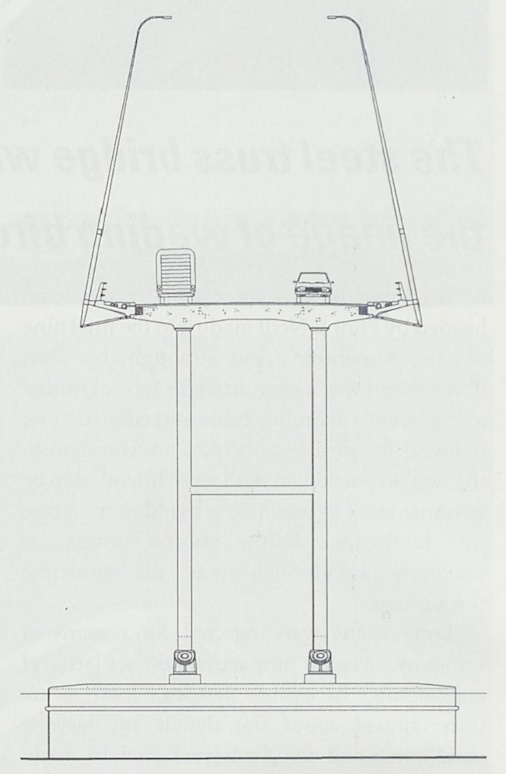
The next cheapest design is a four-span cable-stay bridge, with two main spans of 253m each. The cables are in an intermediate arrangement between the typical harp and fan layouts, supported in two planes from A-frame towers. The bridge deck uses another composite truss as its "spine" (light rail below and footway above, the latter reminiscent of the Brooklyn Bridge), with the road deck cantilevered either side.


The towers are of lower height than is normal in a cable-stayed bridge, presumably because of the presence of an airfield nearby. The report discounts the option of an extradosed bridge, which would have seemed well worth considering for a crossing of this scale.


The report offers little explanation as to why the A-frame and and intermediate cable arrangements were chosen over alternatives, although I can see practical reasons given the desire for the pedestrian and light-rail spine beam, and the extremely wide highway deck (the bridge as a whole is a remarkable 71m wide). The authors also don't comment on the difficulties associated with balancing any multi-span cable-stay bridge: the use of the stiff deck truss is an obvious choice given the cross-sectional requirements, but there are several alternatives.

It's only a specimen design, but it's less well "architected" than the Mersey Gateway or Forth Replacement Crossing designs in the UK, both of which have mono-tower solutions, with the Gateway also adopting the visually less conflicted (but generally more expensive) harp layout for its cables.

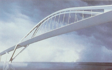
The panel's most expensive option is a triple-arch design, each arch spanning 183m (at deck level, or 221m between foundations). It has two inclined arches, steel tubes filled with concrete. It's no surprise that this design costs the most, as large-span arches are fundamentally more difficult to build than a bridge form which can be cantilevered out gradually from the support piers. The arch is unstable until complete, and so requires the expense of temporary support, either from temporary cable-staying or from trestles supported in the riverbed.


Because these are tied arches, they avoid the problem of unbalanced thrusts on the foundations when alternate spans are loaded with traffic, but at the cost of having to erect the bridge deck (the tie) before the temporary supports can be removed from the arch. This means that the deck also requires temporary support, something that could be avoided by carrying the arch thrust to the foundations instead.

They note that the Y-shaped piers "express the flow of arch compression down to the footings", but if the deck is tied then this is just visual dishonesty. It's not clear if they intend the deck also to act as a tie for the pier arms. I think this aspect of the design is poorly explained - are thrusts on the piers eliminated by the ties, or not, or is it an intermediate situation?


The panel acknowledge the awkward visual balance of three identical arches, noting in their report that an option with a larger central arch and two smaller side arches may be preferable. I think I'd agree with this, the rhythm of three equal arches just doesn't seem to work. The triple-arch bridge is clearly the panel's favourite design, and they note a resonance with the arch bridges of Conde McCullough in the same north-west region of the USA. It's the worst engineering solution, however, and I'm surprised they've put such a small cost premium on it relative to the cable-stayed option.

On the whole, it looks like the design process is at least now proceeding from a firmer basis. It's a challenging bridge to design, given the exceptional width of deck to be supported, and it's interesting that even the independent panel has generally gone for design options with a single central spine rather than two lines of support to the deck - given the very large torsion loads to be resisted, that seems to be an attempt to privilege aesthetics over economy. Hopefully they will carry that through in further design development, as there are a number of visual refinements that can be made at little cost, whichever of the three options is eventually chosen.